Wednesday, November 25, 2009

Easy Abstract Photoshop Tutorial

0 comments

This tutorial will show how to create a very simple abstract shape using a few brushes and effects. For this tutorial I will be using Adobe Photoshop CS3. If you have an older version of Adobe Photoshop, you may still be able to follow this tutorial.

Keep in mind that it would be nearly impossible to duplicate this exact object, but this tutorial should give a guide to creating your own unique object. You should end up with something like this.
adobe photoshop abstract tutorial

The first thing we need to do is download the brush set for this tutorial. You can download the free Trance Brushes from Brusheezy.com by clicking here..

After you download the brushes, extract the .abr file from the .zip and save it.
adobe photoshop abstract tutorial

Open Adobe Photoshop and create a new document 700×700.
adobe photoshop abstract tutorial

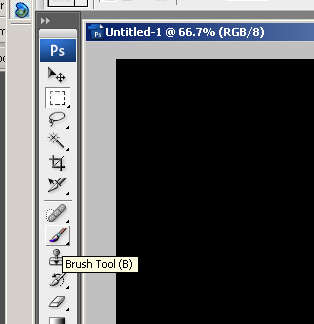
Fill the background layer with black (#000000) and select the brush tool.
adobe photoshop abstract tutorial

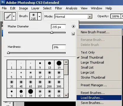
Load the brush set that you just downloaded by clicking the drop down next to the brush > the arrow point right > then the load option.
adobe photoshop abstract tutorial

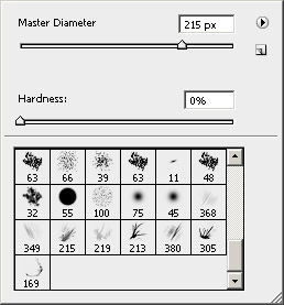
Select the Trance Brushes and load them. You will see the new brushes appear at the bottom of the brush set.
adobe photoshop abstract tutorial

Reset the color swatches so that white is the foreground color and black is the background color. Create a new layer and use some of the brushes to create an abstract shape. When you are painting with these brushes, do not drag the mouse like you normally would. Instead click once to create the shape. There is really no science to this. First I will use brush 305 to create this.
adobe photoshop abstract tutorial

Next I will add a few more with #213.
adobe photoshop abstract tutorial


Then I will use 215 to make a tail.

adobe photoshop abstract tutorial

To complete this shape I will dab a couple times with the brushe that is numbered 380 for me.

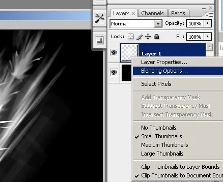
Like I said before, there is no set way to do this, just come up with a shape you like. Now to add a little bit of color I will apple a purple glow. Right click on the layer in the layers pallet and select blending options.
adobe photoshop abstract tutorial

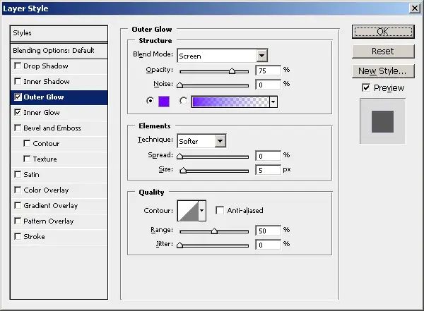
Apply an outer glow using the color #7200ff.
Easy Abstract Photoshop Tutorial

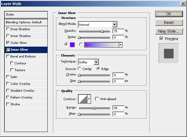
I also added an inner glow using the same color #7200ff.
Easy Abstract Photoshop Tutorial

Apply the changes and you should get something like this.
Easy Abstract Photoshop Tutorial

Now we are going to distort the image using the polar coordinate filter. Click Filter > Distort > Polar coordinates.
Easy Abstract Photoshop Tutorial


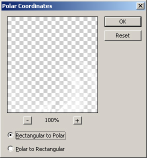
Make sure that Rectangular to Polar is selected and click ok

Easy Abstract Photoshop Tutorial

You will get something like this.
Easy Abstract Photoshop Tutorial

Where the object is located on the canvas will effect how it is distorted. If you do not like the way it came out, undo the filter and move the object. Then try to apply the filter again. Mine looks ok, but I think it is a little blurry.

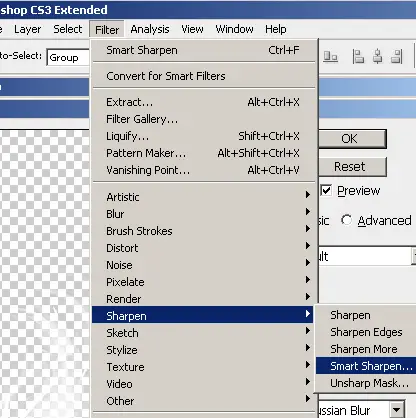
I am going to apply the Smart Sharpen filter to sharpen up the image. Click Filter > Sharpen > Smart Sharpen.
Easy Abstract Photoshop Tutorial

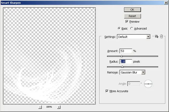
You will have to play with the settings to see what looks the best for you, or you could skip this step completely. Here is what I used.
Easy Abstract Photoshop Tutorial

This is what my image looks like now.
Easy Abstract Photoshop Tutorial

That is all it takes to create a simple abstract shape using brushes. If you do a search online you can some great free brushes to play around with. You could also add some text to this and make into a background or something.
adobe photoshop abstract tutorial

newer post

Thursday, October 22, 2009

NEAX-2400 (PBX / Phone System) Configuration

0 comments

A printable version of this document is also available.

Introduction

Suffield Academy has private branch exchange (PBX) system to facilitate on-campus and external phone calls. We provide dial tone to all student and faculty residences, and also have phone service available to administrative and department offices.

This document describes the basic setup for our phone network, including a general network description, numbering plan, and programming instructions. Finally, a quick reference for end users of the phone system is provided.

Network Setup

Suffield Academy has a block of 440 DID (direct inward dial) extensions that we "own". Outside callers may dial (860) 386-XXXX, where XXXX is one of our 4-digit extensions. Currently, our DID allocations are:

  • 4400 - 4799
  • 1021 - 1060 Internally, we use other extensions outside this range (4000 - 4399 and 4800-4999). While these extensions can make outbound calls, they cannot be dialed directly without being transferred by the switchboard. We keep these numbers for secondary extensions or outward-dial-only devices (automated alarm dialers).

All of these DID numbers are trunked via 2 PRI (primary rate interface) circuits from PAETEC. A PRI is like a T1, but one channel is used for signaling, and is capable of routing a large number of numbers over a smaller number of physical channels (in other words, we only need 46 channels for our 440 DIDs, because the PRI can route and signal the calls on any available channel). The two PRI T1s are sourced from different offices to provide some redundancy. The circuits are:

  • Circuit ID: HCGS.748744 / 20.HCGS.301043.110 (route "10" in the PBX)
  • Circuit ID: HCGS.748731 / 20.HCGS.301044.110 (route "20" in the PBX)

The circuits have the following numbers assigned to them:

  • (860) 752-6526
  • (860) 752-6527
  • (860) 752-6528

These numbers are not routed or listed, but they do come up as the ANI (Automated Number Information) if you request a trace on the circuit. In general, our PBX should provide correct caller ID for our block of DIDs, so you shouldn't see these numbers popping up anywhere.

In addition to these digital lines, we also have 2 POTS (plain old telephone service) lines from AT&T. These are the school's older published phone numbers, and so do not share our 386 prefix. We have a Central Office Line Card (PA-16COT-BE) that these lines connect to. The numbers are:

  • 860 668-7315 (main school number, route "1" in the PBX)
  • 860 668-2966 (main school fax, route "2" in the PBX) In the event that both PRI interfaces are unavailable, outbound calls will fail over to these analog lines.

We provide "off-premise" extensions to phones outside our school-owned network by renting "dry pairs" (or alarm pairs) from AT&T. These lines connect to our PBX, but pass through AT&T's network to reach buildings off campus that we do not provide direct service to. Those lines are:

  • Circuit ID: LCFL.882033 [12,1703,3] (physical plant, Phil Cyr)
  • Circuit ID: LCFL.882039 [12,1711,11] (physical plant, Vinnie Bottone) Those lines are given on-campus extensions, and in all respects appear to be on-campus analog phones. The only difference is that we don't own the copper connecting the phones to our PBX.

Finally, we also order direct service from AT&T for other buildings not served by our network. These lines do not have 386 extensions, as they are not direct-dial extensions. They simply provide basic service to locations we cannot reach:

  • 860 668-1687 (Varnum Physical Plant Building)
  • 860 668-2106 (Day Care)
  • 860 668-5527 (SOLO barn)

PBX Setup

Our PBX is an NEC NEAX-2400 IMX. It serves all on-campus phones, and routes off-campus calls via the PRI interfaces (or, if they are unavailable, any analog lines). The PBX is also capable of many advanced features (caller id, hold, transfers, conference calling, etc.).

The unit itself is located in the school's main server room. The system is modular, and is capable of having additional cards and cabinets added to it over time.

Every line that connects to the PBX is assigned a Line Equipment Number, or LEN (or LENS). These numbers uniquely identify every station on the phone network, and are how the PBX "knows" which phone number is attached to which piece of equipment.

The LENs are assigned according to the location of the card in the PBX that is connected to the line. Our LENs are six digits long, and are comprised of the module, partition, card, and line that serve the particular station.

To determine the LEN, you must determine each of these numbers and concatenate them. If you open the doors to the PBX, you'll see something like the diagram below:

+===============+===============+
| | | -+
| Partition 0 | Partition 1 | |
| | | | Module 01 (top two partitions)
| 010XXX | 011XXX | |
| | | -+
+===============+===============+
| | | -+
| Partition 2 | Partition 3 | |
| | | |
| 000XXX | 001XXX | |
| | | |
+---------------+---------------+ | Module 00 (middle four paritions)
| | | |
| Partition 0 | Partition 1 | |
| | | |
| 000XXX | 001XXX | |
| | | -+
+===============+===============+
| c | p | | | -+
| i a | o | f | CPU 1 | |
| n r | w | d +---------------| | CPU and interface cards
| t d | e | d | CPU 0 | |
| s | r | | | -+
+===============+===============+

The PBX currently has 4 doors. The bottom door contains the two CPUs for the PBX and the interface cards (serial lines to the MAT, voicemail, and SMDR accounting). The door above that contains the bottom half of module 00 (partitions 0 and 1). The door above that contains the top half of module 00 (partitions 2 and 3). Finally, the topmost door contains module 01 (partitions 0 and 1).

These module and partition numbers form the first 3 numbers of the LEN. They are listed in the diagram above. For example, the top left partition's LENs all start with "010", because they are in the top module (module 01), and on the left side (partition 0): 01 + 0 = 010.

In each partition there are several line cards. Above each card there are numbers which determine the group number(s). Sometimes there are 2 group numbers (such as "4 . 5"), sometimes there are 4 group numbers (such as "2 . 3 . 29 . 30"), and sometimes there is a range (such as "12 ~ 15"). The numbers refer to the groups of 8 lines. If there are 2 group numbers, then the card can have up to 16 lines (2 * 8). If there are 4 group numbers, up to 32 lines are possible, but usually only 16 are used (the higher two numbers are discarded). For a range, 8, 16, 24, or 32 lines are available, using numbers from the top of the range first.

The lines themselves are numbered from 0 to 7 in each group, starting from the bottom of the card.

Some examples are in order. Suppose we have a 16-line card in a slot marked "4 . 5". There would be 16 lines total, with LENs ending with 040, 041, 042, 043, 044, 045, 046, 047, 050, 051, 052, 053, 054, 055, 056, 057. Note that the group number (4 and 5) is simply prepended to the line number (0 - 7) to make the final part of the LEN. In the case of single-digit group numbers, a zero is prepended.

Suppose now that we have a 16-line card in a slot marked ("2 . 3 . 29 . 30"). There are still only 16 lines total, and the prefixes "29" and "30" are ignored. The LENs would end with 02(0-7) and 03(0-7).

Finally, suppose we have a 24-line card in a slot marked "12 ~ 15". There are 24 lines total, with prefixes 13(0-7), 14(0-7), and 15(0-7). Note that the prefix "12" is unused, as we start from the top of the range (15) and work downwards. Since there are only 24 lines, we don't need the 12 prefix.

To calculate a complete LEN, you concatenate all of these numbers together. For example, a 24-line card in the top-right cabinet in slot 12 ~ 15 would have LENs in the range 011130 - 011157. You start with the module (01), add the partition (1), then the line card (13, 14, 15, as per the example above), and then the line number (0-7). Note: the last digit in a LEN can only be 0-7, as there can only be a total of 8 lines per group.

The cards themselves come in many sizes and types. Cards with a model number starting with "EL" are digital (capable of supporting NEC Dterm phones), while "LC" cards are analog (work with standard telephones from any vendor). These in turn come in 8, 16, and 24-line sizes. Any other cards in the PBX are specialty cards (PRI, T1, CPU, and other control cards).

System Interfaces

The PBX interfaces with several other systems for control and logging purposes. All of these systems interface via a serial connection (DB-25 or DB-9). There are three main types of connections:

  1. MAT (control terminal, for programming the PBX) on ports 0 and 5
  2. MCI (Message Center Interface, or voicemail) on port 1
  3. SMDR (logging of call accounting data) on port 2, 3, and 4

Note: the SMDR ports buffer data if they are not connected to an output device. If an SMDR station fails and you won't be reconnecting it for a while, you must short the pins to prevent the buffers from filling up. To short the connection on a DB-9 interface, connect the following pins together:

  • Connect pin 2 to pin 3 (SEND)
  • Connect pin 4 to pin 6 (RECEIVE)
  • Connect pin 7 to pin 8 (CTS/clear-to-send)

That should discard data on the interface until a permanent connection is available.

The Frame

Server Room

The frame is where all of the wires from the PBX are connected to the wiring that leads to the individual stations (possibly via other cross-connects in other buildings).

The frame is comprised of numerous 25-pair "split 50" 66 block connectors. Each block has 50 rows with 4 columns of connectors. In every row, the two left connectors are electrically connected, as are the two right connectors. However, the left and right halves are not connected together.

Standard punchdown for a station requires two sets of connectors: either the left or right pair of connectors in two sequential rows. We list the LEN for the station on the top row, and the associated station number (e.g., extension) on the bottom row. For standard white-blue wiring, the white wire (tip) goes on top and blue (ring) on the bottom.

Thus, a sample block might look like the diagram below. The left side shows the label and type of wiring; the right side shows sample numbers as they might appear on the frame (1047 would be LEN 001047, and 4401 would be extension x4401).

LEN label (White/tip) |   A   B   C   D   | 1047
STN label (Blue/ring) | A B C D | 4401

A = punchdown from PBX (left side)
B = punchdown to jack/station (left side)
C = punchdown to jack/station (right side)
D = punchdown from PBX (right side)

When connecting wiring, you will attach the wires to post "B" for the left-hand side and post "C" for the right-hand side. Posts "A" and "D" are already connected to the PBX and should not be used.

Connecting Station Equipment

Wiring is cross-connected from the frame, though a series of equipment boxes to get to the building where the equipment resides. From there, it is cross-connected again to the horizontal cabling in the building, and thus to the individual jack where the equipment will be connected.

In order to connect equipment to the telephone system, the following procedure should be followed:

  1. Activate the extension and LEN in the PBX using the MAT programming software (or, identify an already-active LEN/extension). You will need the LEN to find the cable pair on the frame.
  2. Identify the master cable pair (e.g., pair 537), which corresponds to one of the 110 block cabinets to the right of the frame. For existing numbers, the pair should be listed in the FileMaker phone database. If not, you will need to trace an existing wire (if the LEN/station is already cross-connected), or find the cable pair by building. To find the cable pair by building, you need to know the cable pair in the 110 block for that specific building (usually, a number between 1 and 100). This is where the physical jack (e.g., 34A) is punched down, and should be clearly labed with the jack number and the pair number. Once you know the local building pair (between 1 and 100), you can find the master cable pair. The master pairs run from 1 to 1200, with a contiguous block assigned to each building (the building ranges are marked on the 110 block cabinets). Simply correspond the start of the building block with the number from the building to find the actual master number. For example, Memorial Hall has the master cable pairs 26-100, and building cable pairs 1 - 75. So Memorial's building cable pair 1 corresponds to master cable pair 26, 2 to 27, 3 to 28, and so on.
  3. Cross-connect the master cable pair to the frame using UTP wiring. White wire goes on the top (66 block) and left (110 block), and blue goes on the bottom/right.
  4. If necessary, cross-connect the 110 block to the jack in the building where the equipment should be connected (again, most building pairs are already terminated, so this is only necessary for jacks that don't already have service).

You should now have service on the desired jack.

Programming

Some system changes only require wiring to accomplish (e.g., switching an extension to a new jack). However, most other changes require programming the phone system. This includes assigning new extensions, changing phone type (digital/analog), changing the name display on the phone screens, and many others.

Programming the PBX requires the IMX MAT software from NEC. This software is installed on a machine with a direct serial connection to the PBX. The commands are somewhat arcane, so this section describes frequenly-used commands for common tasks.

Terminology

Several of the commands share input values. Some of these values are always the same (for example "tennant" is always 1), and others use one of a pre-set range of values. We discuss these below.

Restriction Class (RSC)

Our PBX has been set up to allow or deny certain features based on the restriction class of a particular number. Historically, this was used to prevent students from using their phones at certain times of day (study hall and lights out), but these restrictions are currently not used (students can dial at any time).

Restrictions can also be used to allow certain phones to dial numbers, require a PIN for long distance, or perform other tasks. The following table lists the restriction classes in our PBX:

RSC Description
5 Admin (default/PIN required for long-distance)
6 Admin (no PIN for long-distance)
7 Student (enabled - normal operation)
8 Student (default - emergency calls only)
9 Dorm Faculty (no PIN for local calls)

Most lines will either be 5 (admin phones) or 7 (student phones).

Note: RSC 8 ("student default") is not currently used. This restriction class does not allow any calls, except to 911. This class exists for lights out and study hall, but we no longer have the policy of restricting calls during this time.

Service Feature Class (SFC)

The service feature class limits the type of service that a particular phone receives. For example, digital phones support putting calls on hold, transfers, and conference calls. The following table defines the service classes for the types of phones we use:

SFC Description
3 Admin (digital phone)
4 Admin (analog phone)
6 Student (enabled - normal operation)
15 Student (default - emergency calls only)

Most lines will either be 3 (admin phones) or 6 (student phones).

Note: SFC 15 ("student default") is not currently used. This class is a holdover from when we restricted calls during study hall and lights out.

Phone Type (TEC)

Our PBX supports two kinds of phones: standard analog phones (any make or model) and digital phones (NEC Dterm). The digital phones support many additional features (e.g., multiple lines, conference calls, name display).

When a station is created, the type of the line must be specified. One of the following two values must be used:

TEC Description
3 Analog
12 Digital
Station/Extension (STN)

The station is the primary extension of the phone (or, for analog phones, the only extension). We use "station" and "extension" interchangably in this documentation.

Tennancy (TN)

On our system, the tennant is always 1.

Automatic Number Identification (ANI / CPN / Caller ID)

Our PBX connects to the phone company's central office (CO) via a PRI, which is a type of ISDN digital line. As such, our system is more like its own central office than an end customer of the phone company. When our system places calls, it sends out ANI data via the digital line to the CO informing the CO of the station that placed the call.

Because we use "internal-only" (non-DID) extensions, we have to be careful not to send out ANI data for numbers that we do not own. By default, the PBX will send out 860386XXXX, where XXXX is the extension number. We must configure the PBX to override this behavior when we want to send out a different number.

To make matters more confusing, there are 3 types of "caller ID-ish" info that get sent out:

  • ANI (Automatic Number Identification) is used internally by the phone company to determine the owner of the circuit. In our case, ANI is the number of the digital circuit we use (8607526526 from PAETEC). This number isn't even dialable, but it does indicate the owner.
  • CPN (Calling Party Number) is what our PBX has control over. This number is sent out as a data packet when you place a call, and the receiving equipment can see what number you're calling from. This number can be "spoofed" by the PBX (for example, to map outgoing calls back to a main number). This is what we use on our "private" extensions.
  • e911 data is stored in a database with the phone company. It provides additional information (ALI, or Automated Location Information) to emergency dispaters based on the CPN provided by the switch (not ANI). We provide a spreadsheet to the phone company with address, floor, and room data associated with each DID so the dispatcher knows where to send help.

You can call 1-866-MY-ANI-IS to hear an automated recording of your CPN. Despite the name, it really is your CPN (ANI is only reported if CPN is unavailable).

If you want to hear true ANI info, call MCI at 1-800-444-4444. The voice should read you the ANI unless you have specific caller ID information sent via the phone company.

See the ACNP, ACND, and ACPNCL commands below for information on setting the CPN.

Commands

Backup Phone Database

Changes are held in RAM and will not survive a full system reset unless they are stored to the hard drive. Whenever significant changes to the system have been made, you should back them up.

From the MAT software, choose System Backup -> MEM_HDD (Data control between Memory and HDD).

Choose Memory to Hard Disk as the direction.

Check all the boxes for the data that have changed. We don't use Wireless Call Data or ACD Data Memory, so leave those items unchecked.

Some data are associated with a specific Line Processor (LP), and you must enter the number of the LP to back up the data, which is 0 (zero).

Choose Start. The process will begin, and a timer will count. Each individual checkbox will cause a separate process, and will be shown in the log menu. When all of the processes have finised, the screen will un-grey (accept input) and you can return to the main menu.

Display Station Data (DSTN)

If you know a station number (extension), you can find out all associated information (such as LEN, classes, key assignments, etc.). Simply enter the station number and click Get to fetch the associated information.

If you want a listing for a range of stations (instead of just a single number), use LSDT instead to generate a report.

Display of LENS Data (DLEN)

If you know a LEN, you can find all the associated information (such as extension/station number, phone type, and classes).

Simply input the full 6-digit LEN and you'll get back all the associated information.

If you want a listing for a range of LENS (instead of just a single one), use LLEN instead to generate a report.

Assignment of Name Display Data (ANDD)

Use this command to change the name display that screen phones will show for incoming or outgoing calls.

Enter tennant and station. If a name is already assigned, you must delete it first before entering a new value and saving it.

Assignment of Key Data for DTERM (AKYD)

This command allows you to program the 8 or 16 programmable line buttons on a digital phone. The buttons can be programmed to ring, flash, or dial other lines (allowing people to easily answer other lines or transfer calls).

Enter the primary station for the phone you'd like to program. In the grid below the phone information, you can enter operations for the line buttons. The buttons are numbers left-to-right, top-to-bottom, with the top-left being line 1. Line 1 should be the primary extension for the phone.

In general, just copy an existing line to make another line ring on that phone. If you want the line to flash, but not ring, enter "0" in the RG column (instead of 7). If you want the button to speed-dial a number (rather than answer or join the line), enter "2" in the KD column.

We program all digital phones to have the "last" line button (either 8 or 16, depending on model of phone) dial voicemail. So that number should be programmed to speed dial (KD=2) voicemail (STN=4405) but not ring (RG=0).

Assignment of Station Data (ASDT)

This command allows you to create an extension by assigning a station number to a LEN. The LEN must be unassigned; if you need to unassign the LEN, put in the current station number and then say "Y" under DEL. You can then assign a new station to the LEN.

When you create a new extension, you must choose the phone type (TEC), restriction class (RSC), and service feature class (SFC). See the terminology section above for valid values. Note: the LEN is tied to a specific card in the PBX, and the card type determines the kind of phone that can be attached (analog or digital).

If you need to change the restriction classes, but don't need to reassign the LEN or TEC, use the ASCL command below.

If you need to change extension numbers, but don't need to change anything else (LEN, restriction, phone type, etc.), use the ASTN command below.

Assignment of Station Class Data (ASCL)

Assign phone type (TEC), restriction class (RSC), and service feature class (SFC) for an existing extension (if you need to change these values). More frequently, you will use the ASDT command above to create a new extension and simultaneously assign these values.

Assignment of Station Number (ASTN)

If you have an existing station number that you'd like to change, but do not need to change any other features (such as restriction class or phone type), use this command. Simply provide the existing extension and the new extension and the numbers will switch.

If you need to assign a station to a new LEN, use the ASDT command above.

Assignment of Call Forwarding Station Data (ACFS)

Users can set their phone to forward calls to another number if certain conditions are met (all, busy, no answer). This is useful for forwarding calls to voicemail, to another party, or to another number (e.g., a cell phone).

Users can forward their phone by picking up the handset and dialing *5 (all calls), *6 (busy), or *7 (no answer), followed by the number to forward to (4405 is voicemail, or the extension of your choice).

We have assigned the system parameter that dictates that the FORWARDED station's restriction class is used when a call is forwarded. Thus, if Station A is forwarded to a long distance number, and Station B calls Station A, Station B will be prompted for a PIN if Station A would normally need one. If Station A is in a restriction class that does not require a PIN, then all calls (regardless of origin) will forward without needing a PIN.

To cancel forwarding, dial #5 (all calls), #6 (busy), or #7 (no answer).

For this command, enter 1 for TYPE, and use one of the following for SRV:

SRV Description
V All calls
D Don't Answer
B Busy
N Not reachable (unsure what this is for)

You can list the current assigned forwarding status for a range of numbers by using the LCFS command.

Assignment of Authorization Code Data (AATC)

This command allows you to create PINs for users to dial restricted (long-distance) numbers. Depending on the restriction classes defined, the PIN allows dialing to local, domestic, or international numbers.

For ACR, enter 1.

For RSC, use one of the following restrictions, which define the class of numbers that may be dialed with this PIN:

RSC Description
2 domestic and local (e.g., all but international)
3 international, domestic, and local (e.g., all numbers)
9 local only

For SFC, use one of the following:

SFC Description
3 Admin
6 Student

To examine existing PINs, use the LATC command (you can give a range like "0000000 - 9999999", though the report will take several minutes to generate).

Assignment of Date and Time (ATIM)

The clock in the PBX does drift over time, and also requires manual setting during the switch to/from daylight savings time. This command allows you to set the exact date and time.

Assignment of Calling Number Data (ACND)

When the PBX makes a call, it sets the Calling Party Number (CPN) and sends it to the called party (which uses it as caller ID). Additionally, this is the number shown to emergency services when 911 is dialed.

When the PBX makes a call, it sends the station number out as the CPN. However, we only use 4-digit extensions, so these numbers are not really valid as CPN.

ACND allows you to define rules for turning extensions into full CPN data.

The first field is CNP, which is a number from 1 - 255 defining the pattern that you'd like to define (you can define multiple patterns and then assign them with the ACNP command below). We use "1" as our default plan.

The next field is the SKIP, which is how many digits of the extension to get rid of (working left to right). If the skip is 0, the whole extension will be appended to the CPN data. If skip is the same length as the extension (in our case, 4), then the extension will not appear in the CNP at all (useful if you want to wholly replace a number with another one).

Next there is the ADD field, which tells how many digits will be prepended to the extension. This number should equal 10 - (length of extension) + SKIP. In other words, this prefix plus whatever part of the extension you're sending should be 10.

Finally, there is the DC field, which defines the prefix to put in front of all CNP. It should be the same length as the ADD field.

Examples:

If you use 4-digit extensions, and want to send out a standard area code and prefix before the extension number, you would do:

 CNP: (number between 1 and 255)
SKIP: 0 (use whole extension)
ADD: 6
DC: 860386

A call placed from extension 4567 would come through as 8603864567.

If you want to wholly replace a number with another, you say:

 CNP: (number between 1 and 255)
SKIP: 4 (skip all 4 digits of extension)
ADD: 10
DC: 8603864400

Any number that matches this rule will be replaced with the full 10-digit number specified.

Our current ACND values are:

CNP SKIP ADD DC Notes
1 0 6 860386 Default rule (add are and prefix to station number)

See the ACNP command for information about assigning CPN based on the route, and ACPNCL command for overriding the CPN based on the dial prefix.

Assignment of Calling Number Pattern (ACNP)

Once you've defined one or more CNP using ACND above, you need to tell the switch which CNP apply to which numbers. ACNP does this based on the route that the call goes through.

First, you must say whether the route applies to Incoming or Outgoing routes. We want to affect the CPN for outbound calls, so enter O (the letter "oh") here. (Inbound routes would be for a site-to-site setup where you wanted to modify inbound caller ID from a trusted site.)

For RT, you must provide the route number that the calls are going through.

Finally, specify the CNP variable (1 - 255) that you created using the ACND command above.

Once committed, all calls going through the route will apply the pattern you specified.

Our current ACNP values are:

IC/OG RT CNP Notes
O 10 1 Use default CNP for outgoing calls on PRI 1
O 20 1 Use default CNP for outgoing calls on PRI 2

See the ACPNCL command for a way to assign CNP based on the prefix of the station and override this command.

Assignment of Calling Party Number Conversion (ACPNCL)

This command is like a combination of ACND and ACNP; see those commands for a more detailed description of their options.

This command is useful to override the values set by ACNP (which is like a system-wide default) based on the number of the station placing the call. In this way, you can "exempt" a block of numbers from caller ID, or reassign a block to a standard number.

As we use both DID and non-DID numbers, we need to be careful not to send out non-DID extensions as part of our CPN. Our system-wide default is to send this info, so we use ACPNCL to override this default for the blocks of numbers that are not DIDs.

To use the command, you must specify an outgoing route (OGRT) and station prefix (RCPN). RCPN can be a full extension number (so it only applies to that station), or a prefix (for example, "49" would apply to all extensions starting with the digits "49", including 4901, 4902, etc.).

Note: RCPN numbers cannot overlap or override each other. In other words, you cannot make a rule for "42XX", and then try to override with "4234". If you need to do something like this, you need to break the RCPN into smaller non-overlapping prefixes and specify each one.

Click the Get button to look up the information.

You can now specify a SKIP and ADD, just like for ACND.

Finally, you must provide the ACPN, which is the pattern to prepend to the portion of the extension that hasn't been skipped (see the DC field of ACND).

For example, to replace the CPN for all extensions 4900-4999 with a single number, you would use:

OGRT: (route number)
RCPN: 49 (all numbers starting with 49)
SKIP: 4 (remove all 4 digits of the extension from the CPN)
ADD: 10 (prepend with full 10-digit number)
ACPN: 8603864400

Below are our current settings for ACPNCL. Keep in mind that any pattern not matched below will use the default rules specified in ACPN above (in other words, "860386" will be prepended to the station number).

OGRT RCPN SKIP ADD ACPN Notes
10 40 4 10 8603684400 4000-4099 internal-only (PRI 1)
20 40 4 10 8603864400 4000-4099 internal-only (PRI 2)
10 42 2 8 86038644 4200-4299 remap to 4400-4499 (PRI 1)
20 42 2 8 86038644 4200-4299 remap to 4400-4499 (PRI 2)
10 43 2 8 86038645 4300-4399 remap to 4500-4599 (PRI 1)
20 43 2 8 86038645 4300-4399 remap to 4500-4599 (PRI 2)
10 49 4 10 8603864400 4900-4999 internal-only (PRI 1)
20 49 4 10 8603864400 4900-4999 internal-only (PRI 2)
Assignment of Terminal Application Data (ADAI)

This command allows you to (amont other things) change the number of rings before the station forwards to another extension (e.g., to voicemail).

The main things to look for here are the TC fields (timer) and MTC fields (multiplier). The TC fields have two possible values: 3, which means "2 seconds", and 7, which means "8 seconds" (no, that isn't a typo; the keys and their values have nothing to do with each other).

The multiplier fields determine how many total seconds the phone will ring for, based on the TC field.

For example, if TC is 3 and MTC is 8 (our system default), then the phone will ring for 2 x 8 or 16 seconds (approximately). A general rule of thumb is that the called station will hear a full ring cycle (1 ring plus 1 pause at the least, though possibly more if the ring tone is short) about every six seconds. The caller may hear different numbers of rings depending on their provider and some other timing issues.

The field you most likely want to override is 139, which controls the main answer time. You can also tweak 140 ("no answer recall"), or more likely 247 ("blind transfer no answer"), which gets involved if you transfer to another station. The PBX's call-forwarding mechanism does not appear to count as a "transfer", however.

All of the system defaults can be seen by running ASYD and probing the indices listed above (139, 140, 247). The DATA will list a hex value, where the first digit is 3 or 7 (the TC) and the second digit is anywhere from 1 to F (the MTC). ADAI will override these system-wide defaults.

Enter 1 for the MODE, the tennant and station number, and then zero for all other fields (except those you wish to modify). So, to modify the standard ring time, you'd enter a value for 139MTC and 139TC and zero for all the rest.

Voicemail

FIXME: describe recording vacation greeting, changing menus, etc.

User Commands

Our PBX allows users to customize their extension to provide special features or settings. Please note, sections marked "digital phones only" only apply to NEC Dterm multi-line phones (like those found in our administrative offices).

Forwarding Calls (all phones)

Users can forward their calls to another extension, or to our voicemail extension (4405). There are three conditions when you can forward calls, and each is set independently. The conditions are all calls (forward immediately), busy (forward only if you are on the line), and don't answer (forward only if you don't pick up after several rings).

Note: most users forward to voicemail for busy (*5 4405) and don't answer (*6 4405) only.

Pick up the handset and dial one of the following codes, depending on which kind of forwarding you want (if you want more than one kind of forwarding you must repeat these steps for each type you want):

Dial Forwarding type
*5 All calls
*6 Busy
*7 Don't answer

After dialing the code, wait for broken dial tone. Then dial the number you wish to forward to (to forward to voicemail, enter 4405). You will hear a confirmation tone. Hang up the handset.

To cancel forwarding, pick up the handset and dial one of the following codes, depending on which kind of forward you want to cancel (if you want to cancel more than one kind of forwarding you must repeat these steps for each type):

Dial Forwarding type to cancel
#5 Cancel all calls forward
#6 Cancel busy forward
#7 Canclel don't answer forward

You will hear a confirmation tone, at which point the forward has been canceled.

Voicemail (all phones)

To check your voicemail from on campus from your own extension dial 4405 and follow the prompts.

To check your voicemail from on campus from someon else's phone dial 4205, wait for the recorded message to start, and then dial 9 plus your extension.

To check your voicemail from off campus, dial (860) 386-4405. Wait for the recorded message to start, an then dial 9 plus your extension.

Telephone Setup Functions (digital phones only)

Up/Down Arrows

Used to adjust LCD contrast, speaker/receiver volume, and ringer volume.

Feature Key

This key is used to set various features and functions on your telephone. To activate or cancel, press the Feature button first, then the appropriate number.

  • Feature +1 Turns microphone on or off. The MIC button lights when microphone is on.
  • Feature +2 Adjusts handset receiver volume on current call. The LCD displays the current volume (LARGE OR SMALL). Press Feature and 2 to alternate.
  • Feature +3 Selects ringer tone. Your telephone has 4 different ring tones. After pressing Feature and 3, continue to press 3 until desired tone is heard.
  • Feature +4 Adjusts default handset volume. Options are SMALL (low) or LARGE (high). Press Feature and 4 to change.
  • Feature +5 Activates speakerphone capability.
  • Feature +6 Deactivates speakerphone capability.
  • Feature +7 Turns call indicator lamp on or off for incoming call notification. (If turned off, this lamp will still light to indicate message waiting).

System Features

Hold

To place a call on hold: Press Hold button; held line wink flashes. Note: If held line appears on other D-Term stations, the associated LED flashes red slowly.

To retrieve: Lift handset or press Speaker. Press held line. Note: Any station with this line appearance can retrieve the call.

If unanswered: After approximately two minutes, held call will automatically ring back to the phone that places it on hold. Caller does not hear this ringing. To retrieve call, press button for held line. To continue holding call without hearing automatic ringing, press button for held line, then press Hold.

To place a call on Exclusive Hold (cannot be retrieved from other phones): Press Hold twice; line light winks. (Other D-Term telephones show steady red light). To retrieve call: Lift handset; press button for held line. Call can be retrieved only from telephone that put it on Exclusive Hold.

To place call on hold and consult with third party: Ask party to hold (but do not press Hold); press Transfer, hear broken dial tone. Dial number of party you wish to consult. Converse with third party; when they hang up, you will automatically be connected with holding party. If third party does not answer, reconnect to holding party by pressing Transfer again.

Transfering Calls

To transfer a call: Press Transfer. Broken dial tone indicates caller is placed on hold. Dial destination number, wait one second for call to connect, then hang up.

(Optional): You may stay on the line to announce transfer of call. If party does not answer or line is busy, press Transfer to return to holding party.

Conference Calling (aka three-way calls)

To set up three-way conferencing: Establish first call (incoming or outgoing); ask party to hold.

Press Transfer; receive interrupted dial tone (caller is on hold). Dial third party. (If no answer or busy, press Transfer to reconnect to held party.)

When answered, press Conf Button (Conf LED lights). Three-way conference is established. If one party hangs up, other two remain connected. (Conf LED goes out).

newer post

NEAX-2400 (PBX / Phone System) Configuration

0 comments

A printable version of this document is also available.

Introduction

Suffield Academy has private branch exchange (PBX) system to facilitate on-campus and external phone calls. We provide dial tone to all student and faculty residences, and also have phone service available to administrative and department offices.

This document describes the basic setup for our phone network, including a general network description, numbering plan, and programming instructions. Finally, a quick reference for end users of the phone system is provided.

Network Setup

Suffield Academy has a block of 440 DID (direct inward dial) extensions that we "own". Outside callers may dial (860) 386-XXXX, where XXXX is one of our 4-digit extensions. Currently, our DID allocations are:

  • 4400 - 4799
  • 1021 - 1060 Internally, we use other extensions outside this range (4000 - 4399 and 4800-4999). While these extensions can make outbound calls, they cannot be dialed directly without being transferred by the switchboard. We keep these numbers for secondary extensions or outward-dial-only devices (automated alarm dialers).

All of these DID numbers are trunked via 2 PRI (primary rate interface) circuits from PAETEC. A PRI is like a T1, but one channel is used for signaling, and is capable of routing a large number of numbers over a smaller number of physical channels (in other words, we only need 46 channels for our 440 DIDs, because the PRI can route and signal the calls on any available channel). The two PRI T1s are sourced from different offices to provide some redundancy. The circuits are:

  • Circuit ID: HCGS.748744 / 20.HCGS.301043.110 (route "10" in the PBX)
  • Circuit ID: HCGS.748731 / 20.HCGS.301044.110 (route "20" in the PBX)

The circuits have the following numbers assigned to them:

  • (860) 752-6526
  • (860) 752-6527
  • (860) 752-6528

These numbers are not routed or listed, but they do come up as the ANI (Automated Number Information) if you request a trace on the circuit. In general, our PBX should provide correct caller ID for our block of DIDs, so you shouldn't see these numbers popping up anywhere.

In addition to these digital lines, we also have 2 POTS (plain old telephone service) lines from AT&T. These are the school's older published phone numbers, and so do not share our 386 prefix. We have a Central Office Line Card (PA-16COT-BE) that these lines connect to. The numbers are:

  • 860 668-7315 (main school number, route "1" in the PBX)
  • 860 668-2966 (main school fax, route "2" in the PBX) In the event that both PRI interfaces are unavailable, outbound calls will fail over to these analog lines.

We provide "off-premise" extensions to phones outside our school-owned network by renting "dry pairs" (or alarm pairs) from AT&T. These lines connect to our PBX, but pass through AT&T's network to reach buildings off campus that we do not provide direct service to. Those lines are:

  • Circuit ID: LCFL.882033 [12,1703,3] (physical plant, Phil Cyr)
  • Circuit ID: LCFL.882039 [12,1711,11] (physical plant, Vinnie Bottone) Those lines are given on-campus extensions, and in all respects appear to be on-campus analog phones. The only difference is that we don't own the copper connecting the phones to our PBX.

Finally, we also order direct service from AT&T for other buildings not served by our network. These lines do not have 386 extensions, as they are not direct-dial extensions. They simply provide basic service to locations we cannot reach:

  • 860 668-1687 (Varnum Physical Plant Building)
  • 860 668-2106 (Day Care)
  • 860 668-5527 (SOLO barn)

PBX Setup

Our PBX is an NEC NEAX-2400 IMX. It serves all on-campus phones, and routes off-campus calls via the PRI interfaces (or, if they are unavailable, any analog lines). The PBX is also capable of many advanced features (caller id, hold, transfers, conference calling, etc.).

The unit itself is located in the school's main server room. The system is modular, and is capable of having additional cards and cabinets added to it over time.

Every line that connects to the PBX is assigned a Line Equipment Number, or LEN (or LENS). These numbers uniquely identify every station on the phone network, and are how the PBX "knows" which phone number is attached to which piece of equipment.

The LENs are assigned according to the location of the card in the PBX that is connected to the line. Our LENs are six digits long, and are comprised of the module, partition, card, and line that serve the particular station.

To determine the LEN, you must determine each of these numbers and concatenate them. If you open the doors to the PBX, you'll see something like the diagram below:

+===============+===============+
| | | -+
| Partition 0 | Partition 1 | |
| | | | Module 01 (top two partitions)
| 010XXX | 011XXX | |
| | | -+
+===============+===============+
| | | -+
| Partition 2 | Partition 3 | |
| | | |
| 000XXX | 001XXX | |
| | | |
+---------------+---------------+ | Module 00 (middle four paritions)
| | | |
| Partition 0 | Partition 1 | |
| | | |
| 000XXX | 001XXX | |
| | | -+
+===============+===============+
| c | p | | | -+
| i a | o | f | CPU 1 | |
| n r | w | d +---------------| | CPU and interface cards
| t d | e | d | CPU 0 | |
| s | r | | | -+
+===============+===============+

The PBX currently has 4 doors. The bottom door contains the two CPUs for the PBX and the interface cards (serial lines to the MAT, voicemail, and SMDR accounting). The door above that contains the bottom half of module 00 (partitions 0 and 1). The door above that contains the top half of module 00 (partitions 2 and 3). Finally, the topmost door contains module 01 (partitions 0 and 1).

These module and partition numbers form the first 3 numbers of the LEN. They are listed in the diagram above. For example, the top left partition's LENs all start with "010", because they are in the top module (module 01), and on the left side (partition 0): 01 + 0 = 010.

In each partition there are several line cards. Above each card there are numbers which determine the group number(s). Sometimes there are 2 group numbers (such as "4 . 5"), sometimes there are 4 group numbers (such as "2 . 3 . 29 . 30"), and sometimes there is a range (such as "12 ~ 15"). The numbers refer to the groups of 8 lines. If there are 2 group numbers, then the card can have up to 16 lines (2 * 8). If there are 4 group numbers, up to 32 lines are possible, but usually only 16 are used (the higher two numbers are discarded). For a range, 8, 16, 24, or 32 lines are available, using numbers from the top of the range first.

The lines themselves are numbered from 0 to 7 in each group, starting from the bottom of the card.

Some examples are in order. Suppose we have a 16-line card in a slot marked "4 . 5". There would be 16 lines total, with LENs ending with 040, 041, 042, 043, 044, 045, 046, 047, 050, 051, 052, 053, 054, 055, 056, 057. Note that the group number (4 and 5) is simply prepended to the line number (0 - 7) to make the final part of the LEN. In the case of single-digit group numbers, a zero is prepended.

Suppose now that we have a 16-line card in a slot marked ("2 . 3 . 29 . 30"). There are still only 16 lines total, and the prefixes "29" and "30" are ignored. The LENs would end with 02(0-7) and 03(0-7).

Finally, suppose we have a 24-line card in a slot marked "12 ~ 15". There are 24 lines total, with prefixes 13(0-7), 14(0-7), and 15(0-7). Note that the prefix "12" is unused, as we start from the top of the range (15) and work downwards. Since there are only 24 lines, we don't need the 12 prefix.

To calculate a complete LEN, you concatenate all of these numbers together. For example, a 24-line card in the top-right cabinet in slot 12 ~ 15 would have LENs in the range 011130 - 011157. You start with the module (01), add the partition (1), then the line card (13, 14, 15, as per the example above), and then the line number (0-7). Note: the last digit in a LEN can only be 0-7, as there can only be a total of 8 lines per group.

The cards themselves come in many sizes and types. Cards with a model number starting with "EL" are digital (capable of supporting NEC Dterm phones), while "LC" cards are analog (work with standard telephones from any vendor). These in turn come in 8, 16, and 24-line sizes. Any other cards in the PBX are specialty cards (PRI, T1, CPU, and other control cards).

System Interfaces

The PBX interfaces with several other systems for control and logging purposes. All of these systems interface via a serial connection (DB-25 or DB-9). There are three main types of connections:

  1. MAT (control terminal, for programming the PBX) on ports 0 and 5
  2. MCI (Message Center Interface, or voicemail) on port 1
  3. SMDR (logging of call accounting data) on port 2, 3, and 4

Note: the SMDR ports buffer data if they are not connected to an output device. If an SMDR station fails and you won't be reconnecting it for a while, you must short the pins to prevent the buffers from filling up. To short the connection on a DB-9 interface, connect the following pins together:

  • Connect pin 2 to pin 3 (SEND)
  • Connect pin 4 to pin 6 (RECEIVE)
  • Connect pin 7 to pin 8 (CTS/clear-to-send)

That should discard data on the interface until a permanent connection is available.

The Frame

Server Room

The frame is where all of the wires from the PBX are connected to the wiring that leads to the individual stations (possibly via other cross-connects in other buildings).

The frame is comprised of numerous 25-pair "split 50" 66 block connectors. Each block has 50 rows with 4 columns of connectors. In every row, the two left connectors are electrically connected, as are the two right connectors. However, the left and right halves are not connected together.

Standard punchdown for a station requires two sets of connectors: either the left or right pair of connectors in two sequential rows. We list the LEN for the station on the top row, and the associated station number (e.g., extension) on the bottom row. For standard white-blue wiring, the white wire (tip) goes on top and blue (ring) on the bottom.

Thus, a sample block might look like the diagram below. The left side shows the label and type of wiring; the right side shows sample numbers as they might appear on the frame (1047 would be LEN 001047, and 4401 would be extension x4401).

LEN label (White/tip) |   A   B   C   D   | 1047
STN label (Blue/ring) | A B C D | 4401

A = punchdown from PBX (left side)
B = punchdown to jack/station (left side)
C = punchdown to jack/station (right side)
D = punchdown from PBX (right side)

When connecting wiring, you will attach the wires to post "B" for the left-hand side and post "C" for the right-hand side. Posts "A" and "D" are already connected to the PBX and should not be used.

Connecting Station Equipment

Wiring is cross-connected from the frame, though a series of equipment boxes to get to the building where the equipment resides. From there, it is cross-connected again to the horizontal cabling in the building, and thus to the individual jack where the equipment will be connected.

In order to connect equipment to the telephone system, the following procedure should be followed:

  1. Activate the extension and LEN in the PBX using the MAT programming software (or, identify an already-active LEN/extension). You will need the LEN to find the cable pair on the frame.
  2. Identify the master cable pair (e.g., pair 537), which corresponds to one of the 110 block cabinets to the right of the frame. For existing numbers, the pair should be listed in the FileMaker phone database. If not, you will need to trace an existing wire (if the LEN/station is already cross-connected), or find the cable pair by building. To find the cable pair by building, you need to know the cable pair in the 110 block for that specific building (usually, a number between 1 and 100). This is where the physical jack (e.g., 34A) is punched down, and should be clearly labed with the jack number and the pair number. Once you know the local building pair (between 1 and 100), you can find the master cable pair. The master pairs run from 1 to 1200, with a contiguous block assigned to each building (the building ranges are marked on the 110 block cabinets). Simply correspond the start of the building block with the number from the building to find the actual master number. For example, Memorial Hall has the master cable pairs 26-100, and building cable pairs 1 - 75. So Memorial's building cable pair 1 corresponds to master cable pair 26, 2 to 27, 3 to 28, and so on.
  3. Cross-connect the master cable pair to the frame using UTP wiring. White wire goes on the top (66 block) and left (110 block), and blue goes on the bottom/right.
  4. If necessary, cross-connect the 110 block to the jack in the building where the equipment should be connected (again, most building pairs are already terminated, so this is only necessary for jacks that don't already have service).

You should now have service on the desired jack.

Programming

Some system changes only require wiring to accomplish (e.g., switching an extension to a new jack). However, most other changes require programming the phone system. This includes assigning new extensions, changing phone type (digital/analog), changing the name display on the phone screens, and many others.

Programming the PBX requires the IMX MAT software from NEC. This software is installed on a machine with a direct serial connection to the PBX. The commands are somewhat arcane, so this section describes frequenly-used commands for common tasks.

Terminology

Several of the commands share input values. Some of these values are always the same (for example "tennant" is always 1), and others use one of a pre-set range of values. We discuss these below.

Restriction Class (RSC)

Our PBX has been set up to allow or deny certain features based on the restriction class of a particular number. Historically, this was used to prevent students from using their phones at certain times of day (study hall and lights out), but these restrictions are currently not used (students can dial at any time).

Restrictions can also be used to allow certain phones to dial numbers, require a PIN for long distance, or perform other tasks. The following table lists the restriction classes in our PBX:

RSC Description
5 Admin (default/PIN required for long-distance)
6 Admin (no PIN for long-distance)
7 Student (enabled - normal operation)
8 Student (default - emergency calls only)
9 Dorm Faculty (no PIN for local calls)

Most lines will either be 5 (admin phones) or 7 (student phones).

Note: RSC 8 ("student default") is not currently used. This restriction class does not allow any calls, except to 911. This class exists for lights out and study hall, but we no longer have the policy of restricting calls during this time.

Service Feature Class (SFC)

The service feature class limits the type of service that a particular phone receives. For example, digital phones support putting calls on hold, transfers, and conference calls. The following table defines the service classes for the types of phones we use:

SFC Description
3 Admin (digital phone)
4 Admin (analog phone)
6 Student (enabled - normal operation)
15 Student (default - emergency calls only)

Most lines will either be 3 (admin phones) or 6 (student phones).

Note: SFC 15 ("student default") is not currently used. This class is a holdover from when we restricted calls during study hall and lights out.

Phone Type (TEC)

Our PBX supports two kinds of phones: standard analog phones (any make or model) and digital phones (NEC Dterm). The digital phones support many additional features (e.g., multiple lines, conference calls, name display).

When a station is created, the type of the line must be specified. One of the following two values must be used:

TEC Description
3 Analog
12 Digital
Station/Extension (STN)

The station is the primary extension of the phone (or, for analog phones, the only extension). We use "station" and "extension" interchangably in this documentation.

Tennancy (TN)

On our system, the tennant is always 1.

Automatic Number Identification (ANI / CPN / Caller ID)

Our PBX connects to the phone company's central office (CO) via a PRI, which is a type of ISDN digital line. As such, our system is more like its own central office than an end customer of the phone company. When our system places calls, it sends out ANI data via the digital line to the CO informing the CO of the station that placed the call.

Because we use "internal-only" (non-DID) extensions, we have to be careful not to send out ANI data for numbers that we do not own. By default, the PBX will send out 860386XXXX, where XXXX is the extension number. We must configure the PBX to override this behavior when we want to send out a different number.

To make matters more confusing, there are 3 types of "caller ID-ish" info that get sent out:

  • ANI (Automatic Number Identification) is used internally by the phone company to determine the owner of the circuit. In our case, ANI is the number of the digital circuit we use (8607526526 from PAETEC). This number isn't even dialable, but it does indicate the owner.
  • CPN (Calling Party Number) is what our PBX has control over. This number is sent out as a data packet when you place a call, and the receiving equipment can see what number you're calling from. This number can be "spoofed" by the PBX (for example, to map outgoing calls back to a main number). This is what we use on our "private" extensions.
  • e911 data is stored in a database with the phone company. It provides additional information (ALI, or Automated Location Information) to emergency dispaters based on the CPN provided by the switch (not ANI). We provide a spreadsheet to the phone company with address, floor, and room data associated with each DID so the dispatcher knows where to send help.

You can call 1-866-MY-ANI-IS to hear an automated recording of your CPN. Despite the name, it really is your CPN (ANI is only reported if CPN is unavailable).

If you want to hear true ANI info, call MCI at 1-800-444-4444. The voice should read you the ANI unless you have specific caller ID information sent via the phone company.

See the ACNP, ACND, and ACPNCL commands below for information on setting the CPN.

Commands

Backup Phone Database

Changes are held in RAM and will not survive a full system reset unless they are stored to the hard drive. Whenever significant changes to the system have been made, you should back them up.

From the MAT software, choose System Backup -> MEM_HDD (Data control between Memory and HDD).

Choose Memory to Hard Disk as the direction.

Check all the boxes for the data that have changed. We don't use Wireless Call Data or ACD Data Memory, so leave those items unchecked.

Some data are associated with a specific Line Processor (LP), and you must enter the number of the LP to back up the data, which is 0 (zero).

Choose Start. The process will begin, and a timer will count. Each individual checkbox will cause a separate process, and will be shown in the log menu. When all of the processes have finised, the screen will un-grey (accept input) and you can return to the main menu.

Display Station Data (DSTN)

If you know a station number (extension), you can find out all associated information (such as LEN, classes, key assignments, etc.). Simply enter the station number and click Get to fetch the associated information.

If you want a listing for a range of stations (instead of just a single number), use LSDT instead to generate a report.

Display of LENS Data (DLEN)

If you know a LEN, you can find all the associated information (such as extension/station number, phone type, and classes).

Simply input the full 6-digit LEN and you'll get back all the associated information.

If you want a listing for a range of LENS (instead of just a single one), use LLEN instead to generate a report.

Assignment of Name Display Data (ANDD)

Use this command to change the name display that screen phones will show for incoming or outgoing calls.

Enter tennant and station. If a name is already assigned, you must delete it first before entering a new value and saving it.

Assignment of Key Data for DTERM (AKYD)

This command allows you to program the 8 or 16 programmable line buttons on a digital phone. The buttons can be programmed to ring, flash, or dial other lines (allowing people to easily answer other lines or transfer calls).

Enter the primary station for the phone you'd like to program. In the grid below the phone information, you can enter operations for the line buttons. The buttons are numbers left-to-right, top-to-bottom, with the top-left being line 1. Line 1 should be the primary extension for the phone.

In general, just copy an existing line to make another line ring on that phone. If you want the line to flash, but not ring, enter "0" in the RG column (instead of 7). If you want the button to speed-dial a number (rather than answer or join the line), enter "2" in the KD column.

We program all digital phones to have the "last" line button (either 8 or 16, depending on model of phone) dial voicemail. So that number should be programmed to speed dial (KD=2) voicemail (STN=4405) but not ring (RG=0).

Assignment of Station Data (ASDT)

This command allows you to create an extension by assigning a station number to a LEN. The LEN must be unassigned; if you need to unassign the LEN, put in the current station number and then say "Y" under DEL. You can then assign a new station to the LEN.

When you create a new extension, you must choose the phone type (TEC), restriction class (RSC), and service feature class (SFC). See the terminology section above for valid values. Note: the LEN is tied to a specific card in the PBX, and the card type determines the kind of phone that can be attached (analog or digital).

If you need to change the restriction classes, but don't need to reassign the LEN or TEC, use the ASCL command below.

If you need to change extension numbers, but don't need to change anything else (LEN, restriction, phone type, etc.), use the ASTN command below.

Assignment of Station Class Data (ASCL)

Assign phone type (TEC), restriction class (RSC), and service feature class (SFC) for an existing extension (if you need to change these values). More frequently, you will use the ASDT command above to create a new extension and simultaneously assign these values.

Assignment of Station Number (ASTN)

If you have an existing station number that you'd like to change, but do not need to change any other features (such as restriction class or phone type), use this command. Simply provide the existing extension and the new extension and the numbers will switch.

If you need to assign a station to a new LEN, use the ASDT command above.

Assignment of Call Forwarding Station Data (ACFS)

Users can set their phone to forward calls to another number if certain conditions are met (all, busy, no answer). This is useful for forwarding calls to voicemail, to another party, or to another number (e.g., a cell phone).

Users can forward their phone by picking up the handset and dialing *5 (all calls), *6 (busy), or *7 (no answer), followed by the number to forward to (4405 is voicemail, or the extension of your choice).

We have assigned the system parameter that dictates that the FORWARDED station's restriction class is used when a call is forwarded. Thus, if Station A is forwarded to a long distance number, and Station B calls Station A, Station B will be prompted for a PIN if Station A would normally need one. If Station A is in a restriction class that does not require a PIN, then all calls (regardless of origin) will forward without needing a PIN.

To cancel forwarding, dial #5 (all calls), #6 (busy), or #7 (no answer).

For this command, enter 1 for TYPE, and use one of the following for SRV:

SRV Description
V All calls
D Don't Answer
B Busy
N Not reachable (unsure what this is for)

You can list the current assigned forwarding status for a range of numbers by using the LCFS command.

Assignment of Authorization Code Data (AATC)

This command allows you to create PINs for users to dial restricted (long-distance) numbers. Depending on the restriction classes defined, the PIN allows dialing to local, domestic, or international numbers.

For ACR, enter 1.

For RSC, use one of the following restrictions, which define the class of numbers that may be dialed with this PIN:

RSC Description
2 domestic and local (e.g., all but international)
3 international, domestic, and local (e.g., all numbers)
9 local only

For SFC, use one of the following:

SFC Description
3 Admin
6 Student

To examine existing PINs, use the LATC command (you can give a range like "0000000 - 9999999", though the report will take several minutes to generate).

Assignment of Date and Time (ATIM)

The clock in the PBX does drift over time, and also requires manual setting during the switch to/from daylight savings time. This command allows you to set the exact date and time.

Assignment of Calling Number Data (ACND)

When the PBX makes a call, it sets the Calling Party Number (CPN) and sends it to the called party (which uses it as caller ID). Additionally, this is the number shown to emergency services when 911 is dialed.

When the PBX makes a call, it sends the station number out as the CPN. However, we only use 4-digit extensions, so these numbers are not really valid as CPN.

ACND allows you to define rules for turning extensions into full CPN data.

The first field is CNP, which is a number from 1 - 255 defining the pattern that you'd like to define (you can define multiple patterns and then assign them with the ACNP command below). We use "1" as our default plan.

The next field is the SKIP, which is how many digits of the extension to get rid of (working left to right). If the skip is 0, the whole extension will be appended to the CPN data. If skip is the same length as the extension (in our case, 4), then the extension will not appear in the CNP at all (useful if you want to wholly replace a number with another one).

Next there is the ADD field, which tells how many digits will be prepended to the extension. This number should equal 10 - (length of extension) + SKIP. In other words, this prefix plus whatever part of the extension you're sending should be 10.

Finally, there is the DC field, which defines the prefix to put in front of all CNP. It should be the same length as the ADD field.

Examples:

If you use 4-digit extensions, and want to send out a standard area code and prefix before the extension number, you would do:

 CNP: (number between 1 and 255)
SKIP: 0 (use whole extension)
ADD: 6
DC: 860386

A call placed from extension 4567 would come through as 8603864567.

If you want to wholly replace a number with another, you say:

 CNP: (number between 1 and 255)
SKIP: 4 (skip all 4 digits of extension)
ADD: 10
DC: 8603864400

Any number that matches this rule will be replaced with the full 10-digit number specified.

Our current ACND values are:

CNP SKIP ADD DC Notes
1 0 6 860386 Default rule (add are and prefix to station number)

See the ACNP command for information about assigning CPN based on the route, and ACPNCL command for overriding the CPN based on the dial prefix.

Assignment of Calling Number Pattern (ACNP)

Once you've defined one or more CNP using ACND above, you need to tell the switch which CNP apply to which numbers. ACNP does this based on the route that the call goes through.

First, you must say whether the route applies to Incoming or Outgoing routes. We want to affect the CPN for outbound calls, so enter O (the letter "oh") here. (Inbound routes would be for a site-to-site setup where you wanted to modify inbound caller ID from a trusted site.)

For RT, you must provide the route number that the calls are going through.

Finally, specify the CNP variable (1 - 255) that you created using the ACND command above.

Once committed, all calls going through the route will apply the pattern you specified.

Our current ACNP values are:

IC/OG RT CNP Notes
O 10 1 Use default CNP for outgoing calls on PRI 1
O 20 1 Use default CNP for outgoing calls on PRI 2

See the ACPNCL command for a way to assign CNP based on the prefix of the station and override this command.

Assignment of Calling Party Number Conversion (ACPNCL)

This command is like a combination of ACND and ACNP; see those commands for a more detailed description of their options.

This command is useful to override the values set by ACNP (which is like a system-wide default) based on the number of the station placing the call. In this way, you can "exempt" a block of numbers from caller ID, or reassign a block to a standard number.

As we use both DID and non-DID numbers, we need to be careful not to send out non-DID extensions as part of our CPN. Our system-wide default is to send this info, so we use ACPNCL to override this default for the blocks of numbers that are not DIDs.

To use the command, you must specify an outgoing route (OGRT) and station prefix (RCPN). RCPN can be a full extension number (so it only applies to that station), or a prefix (for example, "49" would apply to all extensions starting with the digits "49", including 4901, 4902, etc.).

Note: RCPN numbers cannot overlap or override each other. In other words, you cannot make a rule for "42XX", and then try to override with "4234". If you need to do something like this, you need to break the RCPN into smaller non-overlapping prefixes and specify each one.

Click the Get button to look up the information.

You can now specify a SKIP and ADD, just like for ACND.

Finally, you must provide the ACPN, which is the pattern to prepend to the portion of the extension that hasn't been skipped (see the DC field of ACND).

For example, to replace the CPN for all extensions 4900-4999 with a single number, you would use:

OGRT: (route number)
RCPN: 49 (all numbers starting with 49)
SKIP: 4 (remove all 4 digits of the extension from the CPN)
ADD: 10 (prepend with full 10-digit number)
ACPN: 8603864400

Below are our current settings for ACPNCL. Keep in mind that any pattern not matched below will use the default rules specified in ACPN above (in other words, "860386" will be prepended to the station number).

OGRT RCPN SKIP ADD ACPN Notes
10 40 4 10 8603684400 4000-4099 internal-only (PRI 1)
20 40 4 10 8603864400 4000-4099 internal-only (PRI 2)
10 42 2 8 86038644 4200-4299 remap to 4400-4499 (PRI 1)
20 42 2 8 86038644 4200-4299 remap to 4400-4499 (PRI 2)
10 43 2 8 86038645 4300-4399 remap to 4500-4599 (PRI 1)
20 43 2 8 86038645 4300-4399 remap to 4500-4599 (PRI 2)
10 49 4 10 8603864400 4900-4999 internal-only (PRI 1)
20 49 4 10 8603864400 4900-4999 internal-only (PRI 2)
Assignment of Terminal Application Data (ADAI)

This command allows you to (amont other things) change the number of rings before the station forwards to another extension (e.g., to voicemail).

The main things to look for here are the TC fields (timer) and MTC fields (multiplier). The TC fields have two possible values: 3, which means "2 seconds", and 7, which means "8 seconds" (no, that isn't a typo; the keys and their values have nothing to do with each other).

The multiplier fields determine how many total seconds the phone will ring for, based on the TC field.

For example, if TC is 3 and MTC is 8 (our system default), then the phone will ring for 2 x 8 or 16 seconds (approximately). A general rule of thumb is that the called station will hear a full ring cycle (1 ring plus 1 pause at the least, though possibly more if the ring tone is short) about every six seconds. The caller may hear different numbers of rings depending on their provider and some other timing issues.

The field you most likely want to override is 139, which controls the main answer time. You can also tweak 140 ("no answer recall"), or more likely 247 ("blind transfer no answer"), which gets involved if you transfer to another station. The PBX's call-forwarding mechanism does not appear to count as a "transfer", however.

All of the system defaults can be seen by running ASYD and probing the indices listed above (139, 140, 247). The DATA will list a hex value, where the first digit is 3 or 7 (the TC) and the second digit is anywhere from 1 to F (the MTC). ADAI will override these system-wide defaults.

Enter 1 for the MODE, the tennant and station number, and then zero for all other fields (except those you wish to modify). So, to modify the standard ring time, you'd enter a value for 139MTC and 139TC and zero for all the rest.

Voicemail

FIXME: describe recording vacation greeting, changing menus, etc.

User Commands

Our PBX allows users to customize their extension to provide special features or settings. Please note, sections marked "digital phones only" only apply to NEC Dterm multi-line phones (like those found in our administrative offices).

Forwarding Calls (all phones)

Users can forward their calls to another extension, or to our voicemail extension (4405). There are three conditions when you can forward calls, and each is set independently. The conditions are all calls (forward immediately), busy (forward only if you are on the line), and don't answer (forward only if you don't pick up after several rings).

Note: most users forward to voicemail for busy (*5 4405) and don't answer (*6 4405) only.

Pick up the handset and dial one of the following codes, depending on which kind of forwarding you want (if you want more than one kind of forwarding you must repeat these steps for each type you want):

Dial Forwarding type
*5 All calls
*6 Busy
*7 Don't answer

After dialing the code, wait for broken dial tone. Then dial the number you wish to forward to (to forward to voicemail, enter 4405). You will hear a confirmation tone. Hang up the handset.

To cancel forwarding, pick up the handset and dial one of the following codes, depending on which kind of forward you want to cancel (if you want to cancel more than one kind of forwarding you must repeat these steps for each type):

Dial Forwarding type to cancel
#5 Cancel all calls forward
#6 Cancel busy forward
#7 Canclel don't answer forward

You will hear a confirmation tone, at which point the forward has been canceled.

Voicemail (all phones)

To check your voicemail from on campus from your own extension dial 4405 and follow the prompts.

To check your voicemail from on campus from someon else's phone dial 4205, wait for the recorded message to start, and then dial 9 plus your extension.

To check your voicemail from off campus, dial (860) 386-4405. Wait for the recorded message to start, an then dial 9 plus your extension.

Telephone Setup Functions (digital phones only)

Up/Down Arrows

Used to adjust LCD contrast, speaker/receiver volume, and ringer volume.

Feature Key

This key is used to set various features and functions on your telephone. To activate or cancel, press the Feature button first, then the appropriate number.

  • Feature +1 Turns microphone on or off. The MIC button lights when microphone is on.
  • Feature +2 Adjusts handset receiver volume on current call. The LCD displays the current volume (LARGE OR SMALL). Press Feature and 2 to alternate.
  • Feature +3 Selects ringer tone. Your telephone has 4 different ring tones. After pressing Feature and 3, continue to press 3 until desired tone is heard.
  • Feature +4 Adjusts default handset volume. Options are SMALL (low) or LARGE (high). Press Feature and 4 to change.
  • Feature +5 Activates speakerphone capability.
  • Feature +6 Deactivates speakerphone capability.
  • Feature +7 Turns call indicator lamp on or off for incoming call notification. (If turned off, this lamp will still light to indicate message waiting).

System Features

Hold

To place a call on hold: Press Hold button; held line wink flashes. Note: If held line appears on other D-Term stations, the associated LED flashes red slowly.

To retrieve: Lift handset or press Speaker. Press held line. Note: Any station with this line appearance can retrieve the call.

If unanswered: After approximately two minutes, held call will automatically ring back to the phone that places it on hold. Caller does not hear this ringing. To retrieve call, press button for held line. To continue holding call without hearing automatic ringing, press button for held line, then press Hold.

To place a call on Exclusive Hold (cannot be retrieved from other phones): Press Hold twice; line light winks. (Other D-Term telephones show steady red light). To retrieve call: Lift handset; press button for held line. Call can be retrieved only from telephone that put it on Exclusive Hold.

To place call on hold and consult with third party: Ask party to hold (but do not press Hold); press Transfer, hear broken dial tone. Dial number of party you wish to consult. Converse with third party; when they hang up, you will automatically be connected with holding party. If third party does not answer, reconnect to holding party by pressing Transfer again.

Transfering Calls

To transfer a call: Press Transfer. Broken dial tone indicates caller is placed on hold. Dial destination number, wait one second for call to connect, then hang up.

(Optional): You may stay on the line to announce transfer of call. If party does not answer or line is busy, press Transfer to return to holding party.

Conference Calling (aka three-way calls)

To set up three-way conferencing: Establish first call (incoming or outgoing); ask party to hold.

Press Transfer; receive interrupted dial tone (caller is on hold). Dial third party. (If no answer or busy, press Transfer to reconnect to held party.)

When answered, press Conf Button (Conf LED lights). Three-way conference is established. If one party hangs up, other two remain connected. (Conf LED goes out).
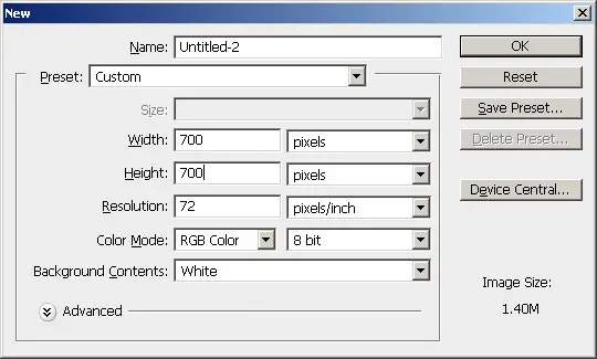
newer post
newer post older post Home

Delete this element to display blogger navbar